2013 KCSE Electricity Past Paper
4.6.1 Electricity Paper 1 (448/1)
SECTION A (48 marks)
Answer all the questions in this section in the spaces provided.
1 (a) Outline the procedure of connecting an ammeter to take a measurement in a circuit.
(b) Figure 1 shows a resistor with colour bands.
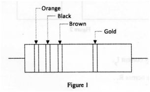
Determine its:
(i) nominal resistance;
(ii) maximum resistance.
2 (a) equipment.
(b) State four components of a bill of materials in project fabrication.
3 (a) Explain the effect of each of the following in a p-n junction:
(i) fonwvard bias;
(ii) reverse bias.
(b) State the meaning of each of the following ratings of a light emitting diode:
(i) lF(max)
(ii) 1F(typ)
4. State two reasons for using a circuit diagram when troubleshooting an electrical
4. Figure 2 shows a transformer whose primary impedance is
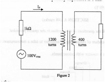
Detemine the:
(a) primary current IP;
(b) voltage across RL.
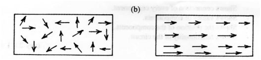
5.With the aid of labelled diagrams, illustrate the arrangement of magnetic domains in:
(a) unmagnetised material;
(b) magnetised material.
6. (a) Figure 3 shows a voltage divider circuit.
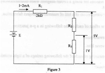
Determine the value of;
(i) E;
(ii) R2;
(iii) R3. (4 marks)
(b) A consumer has the following loads connected to the supply:
(i) five 60 W lights for 4 hours;
(ii) one 2 kW kettle for hour.
Calculate the total:
(i) energy consumed;
(ii) cost of energy used if the rate is 80 cents per unit. (3 marks)
8. a) State three safety precautions to be observed by an operator using a portable electric drill. (3 marks)
(b) Name four communication service provider companies currently operating in Kenya. (2 marks)
9. (a) Name four types of insulating materials used in electrical circuits. (2 marks)
(b) State three advantages of PVC conduit wiring systems. (3 marks)
10. (a) Calculate the inductance required to cause resonance at 150 kl-lz when the capacitance is 1.0 pF. (2 marks)
(b) In a 240V circuit, the load current is 2-5 A. If the power factor is 06, calculate:
(i) apparent power;
(ii) true power.
(3 marks)
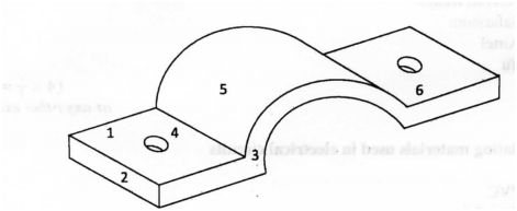
10 . Make a free hand isometric drawing of a conduit saddle. (5 marks)
SECTION B (52 marks)
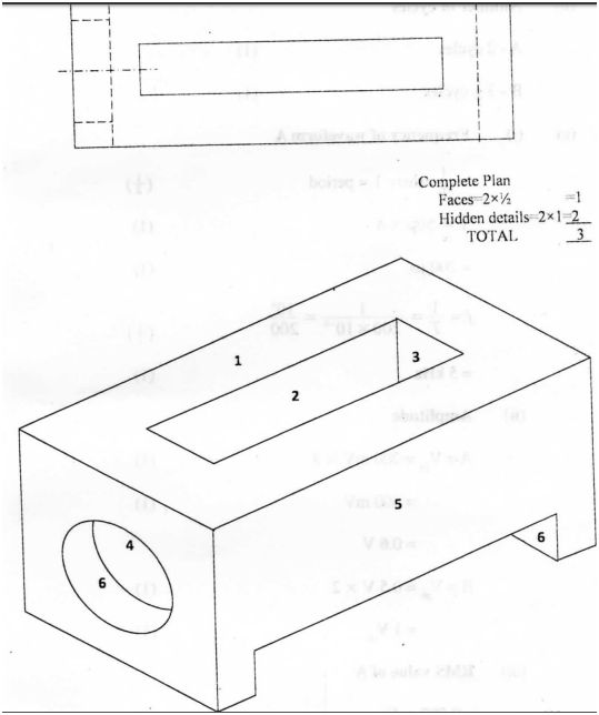
Answer any four questions from this section in the spaces provided. 11Figure 4, in the next page, shows the front elevation, end elevation and an incomplete plan of an object.
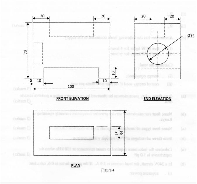
(a) Complete the plan;
(b) On the isometric grid provided, draw the isometric projection of the object making X the lowest point. (13 marks)
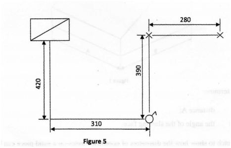
12 Figure 5 shows waveforms A and B. Their vertlcal and honzontal scales are gwen
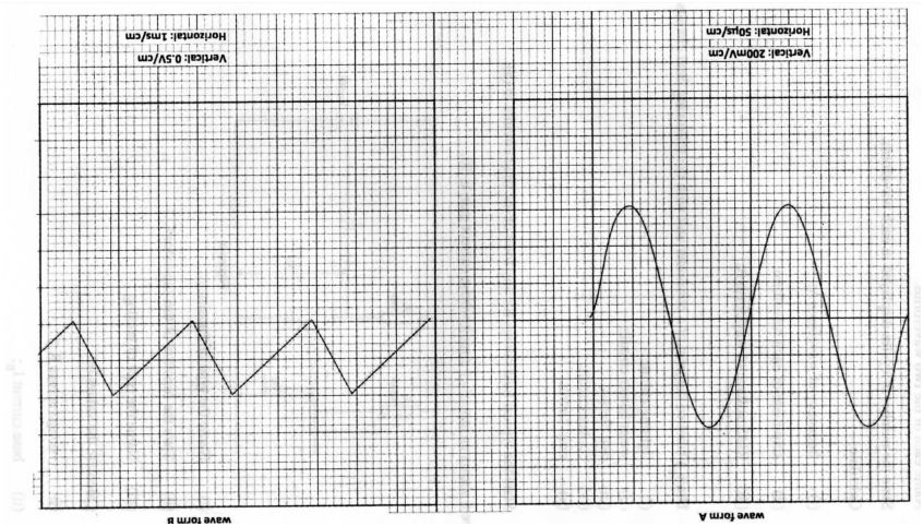
a) Name each of the two wavefonns. (1 mark)
b) State the number of cycles displayed in each waveform. (2 marks)
c) Calculate:
(i) frequency of waveform A;
(ii) amplitude of each waveform;
(iii) RMS voltage of waveform A.
13. Draw a labelled diagram of a consumer unit with the following final circuits.
(i) lighting circuit;
(ii) water heater circuit;
(iii) bell circuit;
(iv) cooker circuit;
(v) ring circuit.
(10 marks)
b) State the typical fuse ratings for any four of the final circuits in (a). (2 marks)
14. Figure 6 shows an amplifier circuit whose current gain is 50.
Figure 6
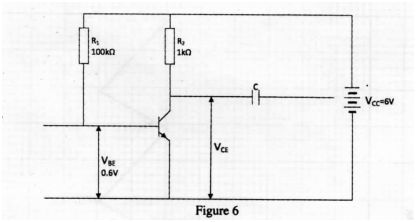
(i) Name the type of transistor;
(ii) State the function of the capacitor C.
(iii) Name the type of biasing.
b) Calculate the values of:
(i) voltage across RI;
(ii) base current IB;
(iii) collector current IC;
(iv) voltage VCE.
15 Figure 7 shows an R-L-C circuit.
R=10QoQ L=5omH C=2}.lF
240V SOHI
Figure 1
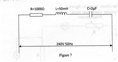
(a) Calculate the:
(i) impedence of the circuit; (7 marks)
(ii) current. (3 marks)
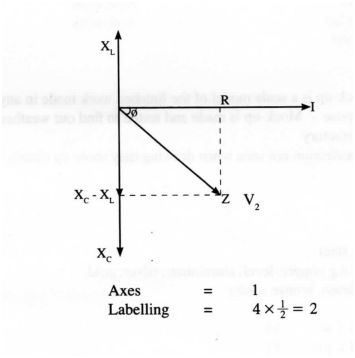
(b) Draw the phasor diagram. (3 marks)
4.6.2 Electricity Paper 2 (448/2)
EXERCISE 1
1 Using materials, components and equipment provided, perform the following tasks.
(i) Correct the circuit shown in figure 1. (3 marks)
Let the examiner check your work.
Potentiometer
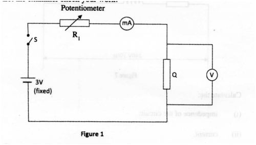
Figure 1
(ii) Close switch S.
(iii) Adjust the potentiometer for the ammeter to obtain current values in table 1 and in each case record the corresponding voltage values. (7 marks)
(iv) Calculate the values of and record them in the spaces provided in the table.
(v) Use the values in the table to draw a graph of voltage against current.
(vi) Determine the slope of the graph. (2 marks)
(vii) From the graph, detennine the voltage, V when the current I = 160 mA.
V = …………………………………………………………………………………… .. (1 mark)
(viii) State the purpose of the experiment. (1 mark)
2. EXERCISE 2
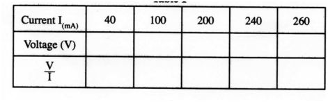
Use the tools, equipment and materials provided to make the bracket shown in figure
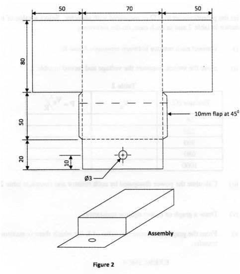
Figure 2
3. EXERCISE 3
Figure 3
Perform the following tasks:
(a) With the switch S open, connect the circuit to the DC power source. Let the examiner check your work. (1 mark)
(b) Set the potentiometer to 0 Q as measured with ohmeter. Select a value of resistor shown in table 2 and in each case, do the following:
(i) connect each resistor between terminals A and B; (2 marks)
(ii) close the switch, measure the voltage and record in table 2. (5 marks)
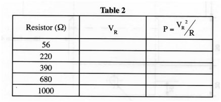
(iii) Calculate the power dissipated by each resistor and complete table 2. (5 marks)
(iv) Draw a graph of power against resistance. (5 marks)
(v) From the graph, detennine the value of R for which there is maximum power transfer. (1 mark)
EXERCISE 4
4. Use the components and equipment to connect the circuit illustrated in figure 4. Let the examiner see your work. (2; 2 marks)
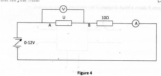
Perform the following tasks:
a) Switch on the power supply.
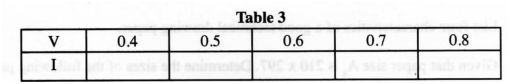
b) Adjust the power supply to obtain each of the voltage values across U as shown in table 3 and in each case, record the corresponding current: (5 marks)
Table 3
c) Switch off the power supply and reverse its connections.
d) Adjust the power supply to obtain each of the voltage values across U as shown in table 4 and in each case, record the corresponding current. (5 marks)
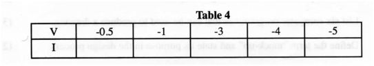
e) Use the values of I and V from tables 3 and 4 to draw the graph of current (I) against voltage (V) on the same axes. (7 marks)
f) From the shape of the graph, identify component U. (4; marks)
EXERCISE 5
5. Figure 5 shows the layout of a lighting installation. Using PVC sheathed cables, install the circuit such that the lamps are controlled at one point.
(20 marks)
2013 KCSE Electricity Past Paper-Marking Scheme/Answers
5.6.1 Electricity Paper 1
SECTION A
1 a) Procedure of connecting an ammeter to take measurements in a circuit
– Tum – off the power
– Amrneter should be connected in series with the load current.
– Observe polarity.
– Select the range starting from the highest.
b) (i) Nominal resistance
Orange Black
3 0
Brown
x 10′ = 300 Q
Nominal = 300 Q
(ii) Maximum resistance
300 + 5% = 315 Q (2 marks)
2. a) Circuit diagram
– Shows connection of every component.
– Shows values of components.
– Shows the position of the components.
– Shows functionality of the circuit.
b) Bills of materials
– Materials/parts.
– Quantity.
– Size.
– Estimate costs.
3. a) (i) Forward bias
reduces the PN-junction (depletion layer) and hence the diode conducts
(ii) Reverse bias
increases the PN-junction (depletion layer) hence the diode does not conduct . (2 marks)
l20OX0l=400> =i= O.3A
E=5+(lXR )
= 5-l-(2XlO’3)<2000)
=5+4
Hm) is the maximum forward current that the diode can pass without burning out. (1 mark)
Drawing
Labelling
Direction
N. 9 V ( 2 )
Fm) is the forward voltage across the diode at the typical operating urr . (1 mark)
5.
b) (i) Energy consumed
Lights S >< 60 x 4 = 1.2 kwh
Kettle l X 2 x 0.5 = 1.0 kwh
Total energy = 2.2 kwh
(ii) Cost of energy
= 2.2 x80 = 1.76 sh
7. Safety precautions to be observed
a) – Ensure that the equipment is properly earthed.
– Donot use itindampareas.
– Always remove the plug from the socket when the equipment is not in use.
– When using extensions, ensure the joints are firm and insulated using the electricians insulation tape.
– Hold it firmly.
– Avoid loose clothing like ties.
b) Communication service providers in Kenya
– Telkom Kenya
– Safaricom
– Airtel
– Yu
or any at/ier existing ones
8. a) Insulating materials used in electrical circuits
– PVC .
– Porcelain
– Magnesium oxide
– Paper
– Rubber
– ‘ Air
– Formica
b) Advantages of PVC
– Easy of erection.
– It is cheap.
– It is resistant to corrosion.
– It is light.
– There is no risk to ea.rth leaks.
9. a) Inductance required
: 1
L 411xfxC
L
41: (1.5 ><10 )x(10- 11)
= 1.13 ><10*=1-1
= l.l3H
b) (i) Apparent power
IV
2.5 >< 240
600 VA
(ii) True power
= apparent power X power factor
600 X 0.6
360 w
10.
11.
12.a) Name of waveforms
A – sine wave
B – saw tooth
b) Number of cycles
A – 2 cycles (1)
B – 3 cycles (1)
(c) (i) Frequency of waveform A
= whereT=period
T= 50p.x4
=2001.1s
,=i=_1?=1_<>‘
T 200X10’° 200
=5k1-1z
(ii) Amplitude
A=VPk=200mV X 3
=600mV
=0.6V
B=V *=0.5V X 2
= 1 VP
(iii) RMS value of A
=0.707 X VP‘
=0.707 x0.6
=0.424V
(13 marks)
13. 5.
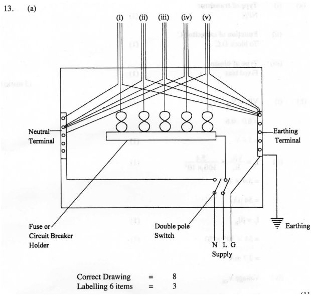
Correct Drawing
Labelling 6 items
Lighting circuit
Ring circuit
Water heater
Door bells
Cooker unit
14 a) Type of transistor
NPN (1)
Function of capacitor C
To block D.C (1)
Typeofbiaslng
Fixedbias (1)
b) VR, =Vm-Vb‘ (1)
=6.0-0.6
=5.4V (1)
<1>
= 5.4 x 10’
=54 A
IC=BIB (1)
=54 X 10‘ X 50 (1)
=2.7mA
Voltage VCE
“R¢=1 X R1 (1)
= 2.7 mA x 1 x 10’
=2.7V (1)
VCE=VCc-VR2 (1)
= 6 – 2.7 V
=3.3V (1)
15. (a) (i) XI. = 27tft. (1)
= 21 0.05 )
=1s.70 Q
N.
Xc nfc (1)
211:><50><2x1O
= 15929
Z= Fimfxi <1>
= <1)
=1s66 Q (1)
(ii) Current = (1)
= 240
1866
=0.l2A Q) Amps
XL
R 1
xc’X
V2
XC
Axes = 1
Labelling = 4